
APPLICATION FIT
Diagnose the scaling problem before selecting PEK softening
PEK softening is not a standalone membrane unit. Engineering assessment must consider scaling ions, reaction conditions, solids loading, sludge destination, and downstream NF, RO, reuse, or ZLD objectives together.
Suitable for initial assessment
Further confirmation required
- Dissolved, colloidal, and particulate silica fractions and their relationship with calcium, magnesium, fluoride, and alkalinity
- Reaction chemicals, target pH, temperature, residence time, and precipitate properties
- Effects of salinity, organics, oil, and other components on reaction, membrane fouling, and cleaning
- Availability of concentrated-sludge handling, dewatering-filtrate routing, chemical storage, and site safety provisions
- Ions and speciation
- Ca, Mg, hardness, silica, fluoride, sulfate, and alkalinity
- Base water quality
- pH, temperature, TDS, SS, COD, oil, and variability
- Operating conditions
- Flow, operating hours, cleaning window, site space, and utilities
- Downstream objective
- Reuse, NF/RO protection, concentration, salt fractionation, or ZLD
PROCESS ROUTE
Organize reaction, solids separation, and downstream protection into one route
The flowsheet explains engineering boundaries and does not require every project to use the same equipment combination. Reaction stages, chemicals, pH readjustment, and sludge treatment depend on actual water chemistry.

View the crawlable text process route
- 01 – Water analysis and equalization – Confirm flow, hardness, silica speciation, fluoride, alkalinity, SS, and variability.
- 02 – Softening / silica-removal / fluoride-removal reaction – Configure alkali, carbonate, or other approved reagents and residence conditions to meet the treatment objective.
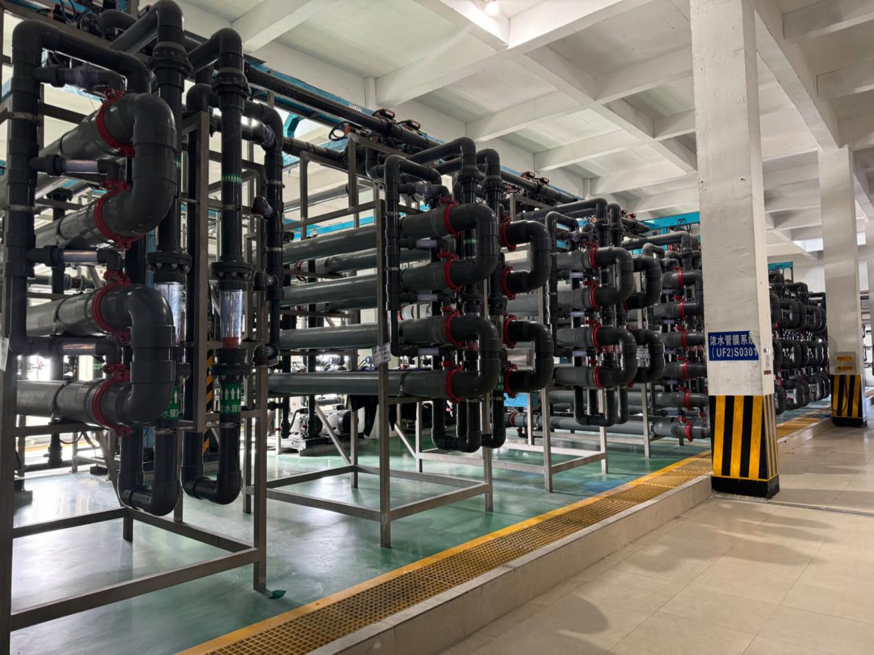
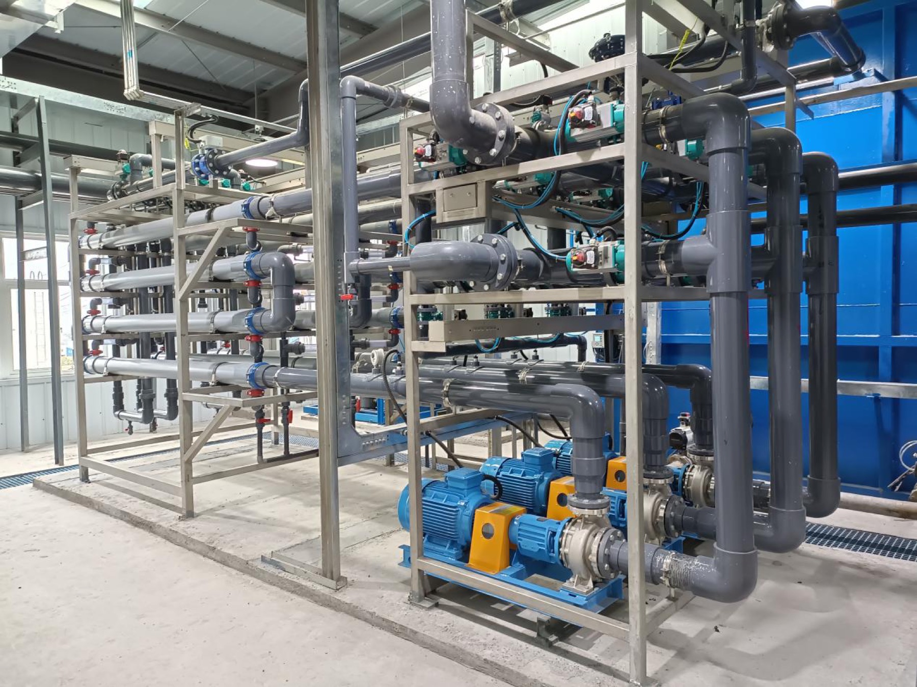
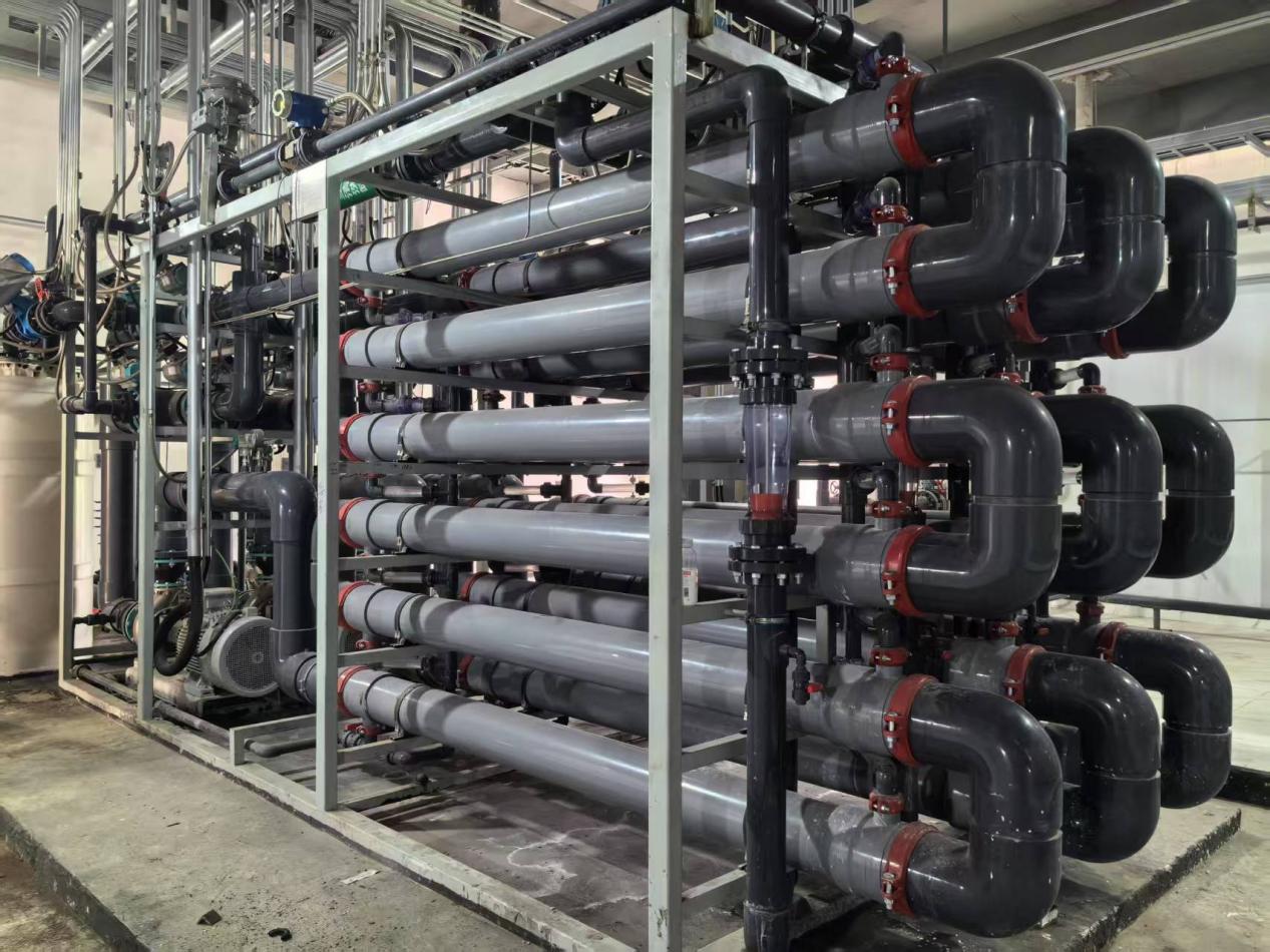
- 03 – PEK tubular membrane cross-flow separation – Continuously retain reaction precipitates, fine particles, and sludge to produce permeate and concentrate.
- 04 – Permeate conditioning and downstream interface – Provide pH readjustment and protection measures required by downstream NF, RO, reuse, or ZLD.
- 05 – Concentrated-sludge handling – Route concentrate to sludge thickening or dewatering; filtrate recycle and discharge boundaries are confirmed separately.
Core engineering principle:First convert target ions into separable solids through reaction, then use the PEK tubular membrane for stable cross-flow solids separation.
REACTION + SEPARATION
The PEK tubular membrane does not directly remove all dissolved ions
Hardness, silica, or fluoride removal first depends on an appropriate chemical reaction that converts target components into precipitates or retainable particles. The PEK tubular membrane then provides high-load solids separation and stable clarification.
- Reaction section
- Select reagents, pH, reaction stages, and residence time based on water chemistry to form separable precipitates.
- Membrane separation section
- Open channels and cross-flow circulation control deposition and retain fine particles, reaction sludge, and suspended solids.
- Downstream section
- Whether the permeate can enter NF, RO, or concentration directly still depends on pH, SDI, residual ions, and downstream equipment requirements.
Therefore, membrane separation capability must not be described as direct adsorption or removal of dissolved hardness, silica, and fluoride by the membrane material.
ENGINEERING BOUNDARY
Use public parameters for screening; confirm project design values separately
Brochure data, public project operating data, and new-project guarantee values are three different evidence levels. This page uses only the first two for engineering screening and does not convert them into new-project commitments.
| Engineering item | Current public reference | Required qualification |
|---|---|---|
| Tubular membrane operating flux | 150–300 LMH | Brochure screening reference; affected by solids properties, temperature, viscosity, circulation, and cleaning conditions |
| Hardness control | Below 50 mg/L in applicable designs | Depends on influent hardness, ionic balance, reagents, pH, and downstream objective |
| Silica control | Below 20 mg/L in applicable designs | Distinguish dissolved, colloidal, and particulate silica and review magnesium, temperature, and reaction conditions |
| Fluoride control | No universal public guarantee value | Determine project values from fluoride concentration, coexisting ions, precipitant, and the target specification |
| Reaction pH and reagents | No universal fixed value | Confirm by jar testing, historical operating data, or pilot validation; pH 11.5 is not assumed for every project |
| Recovery, cleaning cycle, and chemical consumption | No universal commitment | Affected by concentrate handling, recycle arrangement, contaminants, and operating strategy |
The formal solution must define design values, guarantee values, analytical methods, sampling points, operating conditions, and exclusions.
ROUTE COMPARISON
Compare the complete softening and solids-separation route
The value of PEK softening is not simply replacing one filter. It reorganizes post-reaction solids separation, circulation, cleaning, and downstream interfaces.
Softening reaction + settling + multimedia filtration + downstream filtration
- Separation basis
- Relies more heavily on floc settling, filtration loading, and coordination between multiple equipment stages.
- Operating focus
- Settling tanks, media backwash, filtration precision, and downstream membrane protection require separate management.
- Application boundary
- May remain appropriate where water quality is stable, settling is effective, or existing facilities can be reused.
Softening reaction + PEK tubular membrane cross-flow solids separation
- Separation basis
- Use cross-flow membrane separation to retain fine precipitates and sludge, reducing dependence on natural settling.
- Operating focus
- Shift operating focus to reaction windows, circulation hydraulics, membrane flux, concentration factor, and CIP strategy.
- Application boundary
- Whether settling or filtration equipment can be reduced must be determined from water chemistry, solids loading, and site conditions.
Both routes require proper handling of reaction sludge. A tubular membrane does not eliminate chemical reaction or sludge-disposal requirements.
SOLUTION SCOPE
Define the solution scope before discussing equipment and commercial terms
The following are typical boundaries to confirm during preliminary assessment and do not mean that every project automatically includes all equipment or services.
Core membrane section
- Process screening and preliminary membrane-area calculation
- PEK tubular membrane modules and cross-flow circulation unit
- Filtration, discharge, CIP, instrumentation, and control interfaces
Optional engineering scope
- Reaction, dosing, equalization, and required pH readjustment
- Sludge thickening, dewatering, and filtrate recycle
- Downstream NF, RO, and ZLD interfaces plus commissioning services
Owner / EPC interfaces
- Civil tanks, site piping, utilities, and chemical storage
- Off-site sludge disposal or resource-recovery route
- Local standards, safety requirements, and plant-wide interlocks
Final scope, design responsibilities, guarantee boundaries, and interface conditions are defined in the mutually approved technical and commercial documents.
APPLICATION ROUTES
The same membrane section requires different reaction conditions for different water sources
The six water-source categories below are suitable for preliminary assessment, but cannot share one reagent program, flux, recovery, or permeate specification.
Municipal reclaimed water and RO brine
Control hardness and silica to provide stable permeate for reuse, NF/RO concentration, or ZLD pretreatment.
Cooling tower blowdown
Manage hardness, salinity, and turbidity variation caused by evaporation concentration and protect downstream reuse membranes.
Mine water
Define the softening and solids-separation route around hardness, silica, and deep-concentration objectives.
Coking and high-silica industrial wastewater
Focus on silica speciation, the high-salinity background, and silica-scaling risk in RO or evaporation.
FGD wastewater and ZLD
Serve as an upstream softening and solids-separation section in a complex ZLD route, interfacing with fractionation, concentration, and evaporation.
High-fluoride water and metallurgical wastewater
Validate the reaction route and final treatment objective based on fluoride, metal ions, and coexisting salts.
PROJECT EVIDENCE
Support preliminary screening with comparable water sources, capacities, and downstream objectives
Customer names are anonymized. Only capacities, routes, and project directions documented in existing public material are shown; every new project requires independent calculation.
Municipal reclaimed water + RO brine
Softening of 235 m³/h reclaimed water and 106 m³/h Phase-I RO brine
- Route
- Softening reaction → PEK tubular membrane
- Public record
- Commissioned in 2020; recorded project flux 150–200 LMH

Coking wastewater
Silica removal and softening for 40 m³/h high-silica, high-hardness wastewater
- Route
- Softening and silica-removal reaction → PEK tubular membrane
- Public record
- Commissioned in 2023; recorded project flux 150–200 LMH
Mine water
Silica removal, polishing, and softening for 60 m³/h mine water
- Route
- Softening and silica removal → PEK tubular membrane
- Public record
- Commissioned in 2024; recorded project flux 150–200 LMH
Reference data describes existing projects and does not guarantee performance for different water chemistry, capacity, or operating conditions.
RESOURCES
Selection resources and next steps
ProductPEK tubular membrane details
Public resourceTubular membrane brochure
TECHNICAL FAQ
PEK softening frequently asked questions
Does the PEK tubular membrane directly remove dissolved hardness and silica?
No. Hardness, silica, or fluoride is normally converted into precipitates or retainable particles through an approved chemical reaction before PEK tubular membrane cross-flow solids separation. Both reaction and membrane separation are required.
Why use a tubular membrane after the softening reaction?
The reaction can form fine, poorly settling solids with variable loading. Open-channel cross-flow tubular membranes provide continuous solids separation and can serve as clarification ahead of NF, RO, or ZLD.
Can 150–300 LMH, hardness below 50 mg/L, and silica below 20 mg/L be used directly as design values?
No. These are public screening references. Formal design requires actual water chemistry, reaction testing, operating temperature, solids loading, circulation conditions, and downstream objectives, with defined guarantee conditions and analytical methods.
Which projects should begin with jar testing, bench testing, or pilot validation?
Validate reaction windows and membrane-separation stability first when silica speciation is unclear; fluoride or multiple metal ions are present; salinity or organics are high; the reagent route is uncertain; sludge is complex; or downstream requirements are sensitive.
What does a PEK softening process solution typically include?
Assessment normally covers reaction, membrane separation, circulation, CIP, instrumentation and control, and sludge interfaces. Dosing, reaction tanks, sludge dewatering, pH readjustment, downstream membrane sections, and site services depend on the formal technical boundary.
What data is required for preliminary assessment?
Provide at least flow, temperature, pH, total hardness, calcium, magnesium, total silica and silica speciation, fluoride, sulfate, alkalinity, TDS, SS, COD or oil, existing process, downstream objective, and acceptable sludge-handling method.
PEK SOFTENING EVALUATION
Submit water chemistry and downstream objectives for preliminary softening-route assessment
Upload a complete water-analysis report and existing process diagram where possible. The engineering team will first assess the reaction route, membrane-separation fit, missing data, and whether validation is recommended.
Submitted information is used only for preliminary project assessment. Final process, reagents, parameters, treatment performance, scope, and guarantee conditions are defined in the formal technical documents.